RF Magnetron Sputtering 증착법을 이용한 TiO2/SiO2/ZrO2 박막 특성 연구

초록
산업현장에서 사용하는 작업용 보안경, 일반 시력보정용 안경 및 각종 광학기기 등에서 필요한 방담성(antifogging)을 갖는 친수성 박막을 제작하고 박막의 특성을 연구하고자 한다.
RF magnetron sputtering 증착법으로 TiO2, SiO2, ZrO2 등의 코팅재료를 이용하여 단일박막과 각 소재의 조합으로 다층박막을 제작하며, Substrate는 Slide glass를 사용하였고, 진공도는 4.0 × 10⁻² torr, RF-power는 70 W, 기판과의 거리는 80 mm 등의 박막공정으로 증착하여 광학적, 기계적 특성을 분석하였다.
제작된 광학박막의 형태 및 결정성분 분석을 위해 SEM, AFM을 이용하여 분석하였고, 화학적 조성분석을 위해 SEM-EDS를 이용하였고, 광투과율은 UV-visible spectrophotometer, 접촉각은 Contact angle analyzer를 이용하여 분석하였다.
광학박막의 최외층이 SiO2, TiO2 단일박막, 다층박막일 때 다른 조건의 광학박막에 비해 방담성이 우수한 것으로 확인되었으며, RF 마그네트론 스퍼터링이 안경렌즈 및 광학기기 등의 광학적 성능을 향상시키기 좋은 증착법임을 확인하였다.
Abstract
To study the antifogging properties of thin films required for safety goggles used in industrial applications, general vision correction glasses, and various optical instruments.
A radio frequency (RF) magnetron sputtering method was used to fabricate multilayer thin films composed of a stack of individual thin films sputter-coated from materials such as TiO2, SiO2, and ZrO2. Glass slides were used as the substrates. The sputtering vacuum was set to 4.0 × 10⁻² torr, RF-power was 70 W, and the distance between the target and the substrate was 80 mm. The optical and mechanical properties of the optical film samples were analyzed.
Scanning electron microscopy (SEM) and atomic force microscopy (AFM) was used to analyze the morphology and crystal nature of the fabricated optical thin films. SEM-energy dispersive x-ray spectroscopy (SEM-EDS) was used for chemical composition analysis. The light transmittance was measured using a UV-visible spectrophotometer and contact angle was analyzed using a contact angle analyzer.
When the outermost layer of the optical thin film was SiO2, a TiO2 single thin film, or a multilayer thin film, antifogging properties were superior to optical thin films fabricated under other conditions. We confirmed that RF magnetron sputtering was an excellent deposition method to improve the optical performance of spectacle lenses and optical instruments.
Keywords:
RF magnetron sputtering, TiO2, SiO2, ZrO2, Optical thin film키워드:
RF magnetron sputtering, TiO2, SiO2, ZrO2, 광학박막서 론
최근 광학분야에 사용되는 광학소재의 개발과 함께 재료가 지닌 고유의 특성을 개선하는 연구가 광범위하게 진행되고 있으며,[1-6] 기존의 광학재료가 지닌 특성에 별도의 기능을 추가하거나 특정 물성을 향상시키기 위해 물질을 첨가하는 등의 연구에 관심이 높아지고 있다.[7-10] 소재 개발과 더불어 광학소재의 광학적, 기계적 특성을 향상시키는 광학박막 제작기술에도 연구가 다양하게 이루어지고 있다.[11,12] 나노 수준의 얇은 막을 이용하는 박막기술은 재료 및 소재분야와 반도체 등의 전기전자분야, 생명과학분야 등 광범위하게 이용되고 있다. 기존의 소재로는 구현하기 어려운 광학적, 기계적 특성을 갖는 광학소재는 주로 광학박막을 이용하여 요구하는 수준으로 향상하는데, 투과율, 반사율, 편광, 위상 등 광학적 특성을 조절하여 소재표면을 조건에 맞게 증착시킨다.[13,14]
본 연구에서는 산업현장에서 사용하는 작업용 보안경과 각종 광학기기 등에서 필요한 방담성(anti-fogging)을 갖는 광학박막을 제작하였다. 일반적인 시력보정용 안경뿐만 아니라 근로자들이 작업시 착용하는 작업용 보안경의 사용시 가장 불편한 점이 렌즈 표면에 발생하는 김서림이었다.[16] 렌즈의 김서림은 렌즈 표면에 친수성 박막을 증착함으로서 해소할 수 있는데,[17] 일반적으로 친수성 박막은 물의 퍼짐 현상이 발생하여 빠른 건조, 표면의 이물질제거, 미세먼지의 재흡착방지 등 자가세정능력을 갖고 있다.[18] 친수박막 제조방법으로는 주로 졸-겔(sol-gel)법,[19-21] 전자빔증착법, 화학기상증착법, 열증착법, 스퍼터링법[22]등을 이용하는데, 졸-겔법이나 화학기상증착법은 설치비가 저렴하고 작업공정이 적어 편리하지만, 제작 조건의 변화가 다양하여 공정 재현성이 떨어지는 단점이 있다. 이에 반해 스퍼터링법은 내구성이 우수하고, 매우 조밀하고 균일한 박막을 제작할 수 있으며 높은 증착속도, 낮은 진공도에서 박막제작, 증착 타겟(target)의 다양화 등의 장점이 있어 산업현장에서 많이 활용되고 있다.[23,24]
대상 및 방법
1. 대상 및 실험방법
투과율이 우수하고 물리적, 화학적으로 안정하며 기계적 특성이 우수하여 광학박막 소재로 많이 활용하는 TiO2, SiO2, ZrO2를 이용하여 타겟과 기판의 간격을 80 mm로 고정하고 알곤(Ar) 가스를 주입하여 글래스에 RF(고주파)마그네트론 스퍼터링(magnetron sputtering) 증착법[15,25]을 이용하여 단일박막(single layer)과 이중박막(double layer), 그리고 다층박막(multi layer: TiO2/SiO2/ZrO2/glass)을 제작하였다.[26-28] 우수한 광학적 성능을 위해 높은 광투과율을 갖는 무반사코팅(anti-reflection coating) 조건하에서 박막을 증착하기 위해 에센셜 맥클라우드(Essential Macleod) 소프트웨어를 이용하여 박막의 최적의 광투과율을 갖는 조건을 확인하고, 각 레이어에서의 기계적 특성과 광학적 특성을 확인하였다.
본 연구에서는 RF 마그네트론 스퍼터링으로 증착된 TiO2, SiO2, ZrO2 단일막의 굴절률과 미세구조 특성을 분석한 후 최적 조건을 만족하고 우수한 증착속도와 증착율을 구현할 수 있는 단일막 공정 조건을 확인한 후, Table 1에 나타낸 것과 같은 공정조건을 바탕으로 우수한 광학적 기계적 특성을 갖는 다층박막으로 증착하여 단일박막과 다층박막에 따른 방담효과와 성능을 측정하였다.[29-36]
2. 측정기기 및 분석
분광광도계(UV-visible spectrophotometer; Thermo Scientific Co.)를 사용하여 광학적 특성을 분석하는데, 200~800 nm 파장대의 영역에서 광 투과율과 반사율을 측정하였으며, 구조적 특성은 전자주사 현미경(SEM; Tescan Co.) 이미지를 통해 단면과 표면의 상태를 관찰하였고, 또한 SEM장치에 별도의 EDS를 부착하여 시료의 구성 물질을 분석하였다. 원자힘 현미경(AFM; Parker Systems)으로 광학박막의 표면거칠기 등을 관찰하고, 친수성을 알아보기 위해 접촉각 측정기(Contact angle analyzer; Kruss Co.)를 이용하였다.
결과 및 고찰
1. 광학박막의 형태 및 결정성 분석
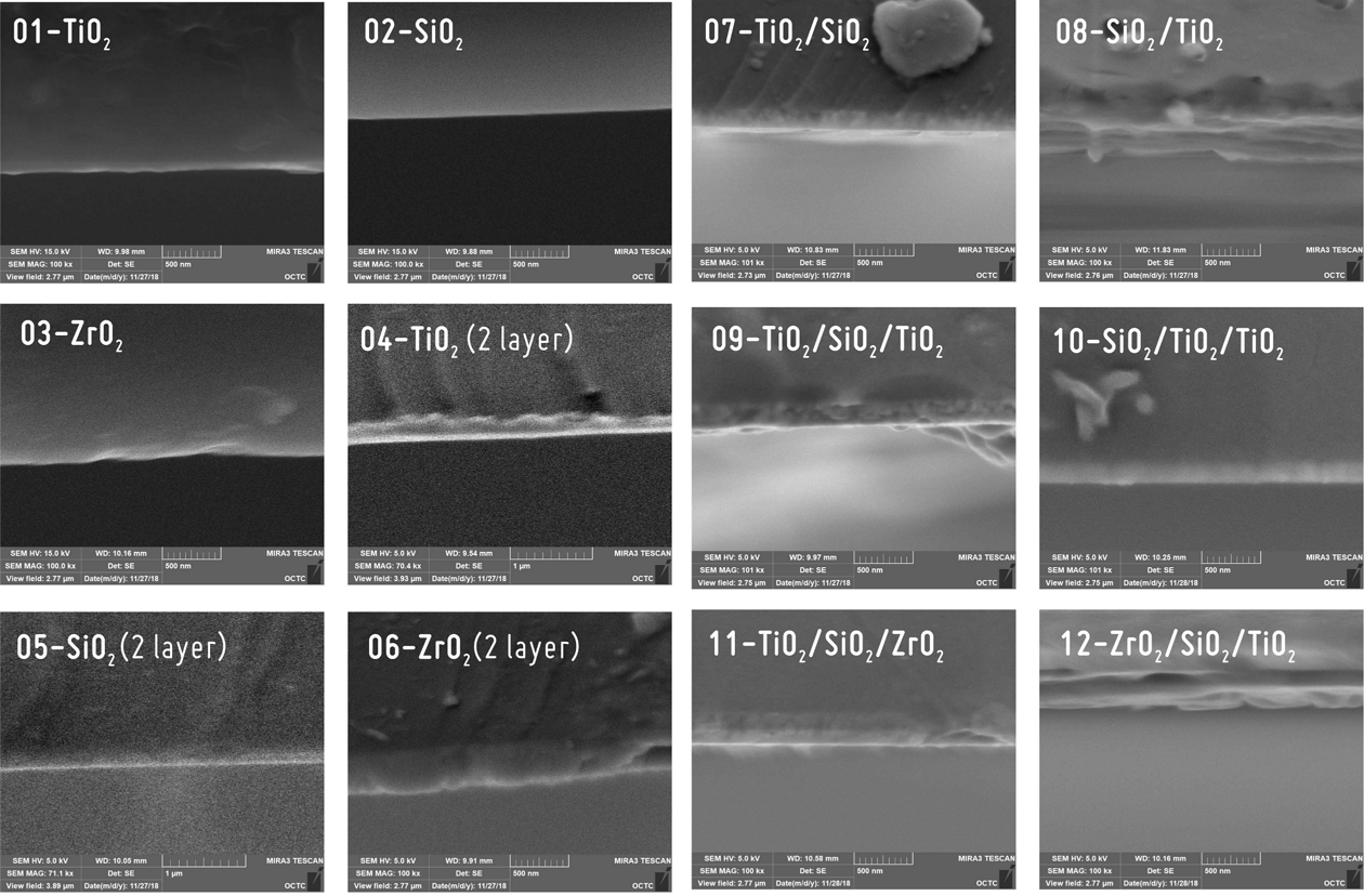
증착된 광학박막의 형태 및 결정성을 분석하기 위해 Fig. 1과 같이 SEM으로 박막 단면을 분석하였다. RF 파워 70 W에서 약 60분간, 시료와 타겟 간격 80 mm로 스퍼터링한 광학박막 기판 12종을 주사전자현미경(SEM; Tescan Co.)을 이용하여 5~15 kV, 7만~10만 배율의 조건으로 분석하였다. TiO2, SiO2, ZrO2 단일박막의 단면 이미지와 TiO2, SiO2, ZrO2 단일박막의 2배에 해당하는 두께를 갖는 2 layer 박막과 TiO2/SiO2와 같은 이중박막, TiO2/SiO2/ZrO2와 같은 다층박막 등의 단면 이미지를 분석하였다. SEM 이미지에서 확인할 수 있듯이 각 타겟의 물질이 기판에 고르고 안정적으로 부착되어 있음을 알 수 있다.
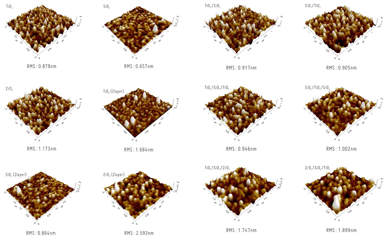
Fig. 2는 RF 마그네트론 스퍼터링으로 증착한 광학박막의 원자힘 현미경(AFM; Parker Systems Co.) 분석 결과이다. 스퍼터링 증착을 하지 않은 글래스(bare glass) 기판의 표면 분석한 결과값은 표면거칠기값 RMS(root mean square)가 0.543 nm이었고, TiO2, SiO2, ZrO2 단일박막의 RMS값은 각각 0.879 nm, 0.657 nm, 1.173 nm로 나타났다. 단일박막의 두께가 TiO2가 95.02 nm, SiO2가 95.06 nm, ZrO2가 101.45 nm이고 2 layer 박막의 두께는 TiO2가 191.12 nm, SiO2가 190.88 nm, ZrO2가 205.09 nm이었으며, 단일박막을 2 layer로 증착하여 박막두께가 더 두꺼운 TiO2, SiO2, ZrO2 이중박막은 각각 1.684 nm, 0.864 nm, 2.593 nm로 단일박막의 RMS에 비해 더 증가한 것을 알 수 있다. 박막의 두께가 증가함에 따라 박막의 표면거칠기 RMS값도 함께 증가하였다.
TiO2/SiO2, SiO2/TiO2 이중박막은 각각 RMS의 값이 0.917 nm, 0.905 nm로 최외층의 물질이 SiO2와 TiO2로 RMS의 값이 SiO2가 0.657 nm, TiO2가 0.879 nm에서 조금씩 증가하였다. TiO2/SiO2/TiO2, SiO2/TiO2/SiO2 다층박막의 RMS값은 0.946 nm, 1.002 nm로 최외층이 TiO2와 SiO2로 단일박막일 때의 RMS값 0.879 nm, 0.657 nm에서 조금씩 증가하였음을 알 수 있다. 또, TiO2/SiO2/ZrO2, ZrO2/SiO2/TiO2 다층박막의 RMS값은 1.747 nm, 1.899 nm로 단일박막에 비해 조금씩 증가하였다. 박막의 표면거칠기 RMS가 클수록 유효 표면적이 증가하므로 방담효과가 더 우수할 것으로 예상할 수 있다.
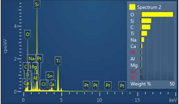
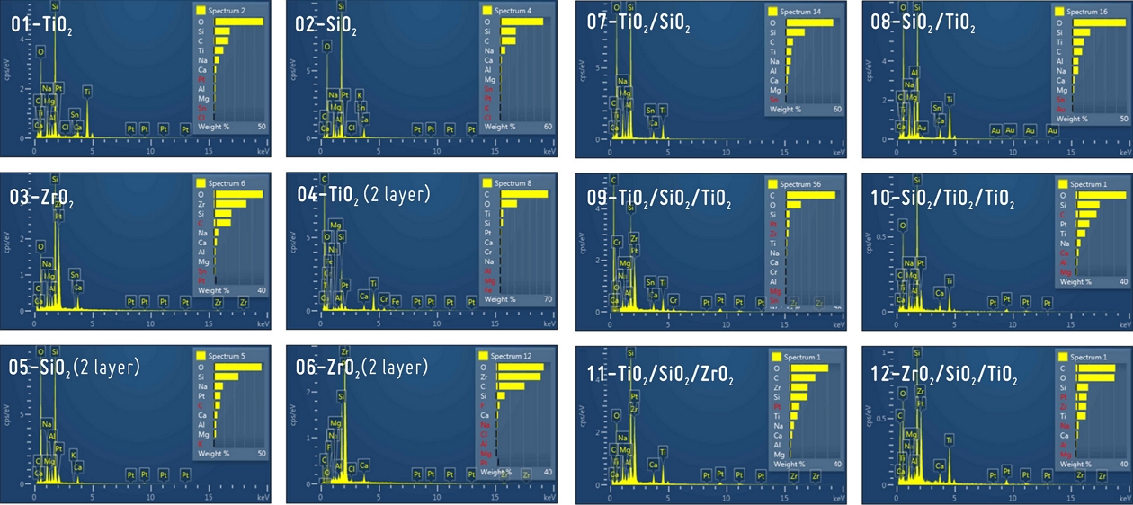
에너지 분산형 분광분석기(EDS; Tescan Co.)는 시료의 구성 물질을 분별하는 방법으로 SEM 장치에 별도로 부착하여 분석한다. SEM-EDS는 광학박막의 표면에 증착된 물질이 어떤 성분으로 구성되어 있는지 정성적, 정량적 분석이 가능하다. Fig. 3과 같이 TiO2 박막에 포함된 물질을 그래프와 표로 나타낸다. 유리 기판에 증착하여 Si 물질이 검출된 것으로 보이며, EDS 분석 시 기본 검출되는 노이즈 물질인 C물질과 단층면을 안정적으로 스캔하기 위해 최외층에 스퍼터링한 Pt가 같이 검출된 것을 알 수 있다. SEM-EDS 분석 시 진공상태에서 측정을 하는데 증착물질을 검사할 때 노이즈가 발생하거나 증착물이 흔들릴 수 있어 최외층을 단단하게 고정하기 위해 Pt나 Au물질을 이용해 약 5 nm 정도의 두께로 커버링을 한다. 그 외 검출된 물질은 실제 존재하는 물질이기 보다는 노이즈 물질로 분석된 것으로 보인다. Table 2는 스퍼터링법으로 증착한 광학박막의 EDS의 정량 분석 데이터이다. Fig. 4는 광학박막의 EDS 분석 이미지들을 나타내었다. 다층박막의 경우 최외층의 증착물질이 검출된 것을 확인할 수 있다.
2. 광학박막의 광학적 특성
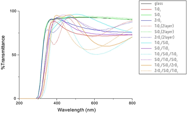
박막의 광학적 특성을 알아보기 위해 Fig. 5와 같이 자외선-가시광선 분광광도계(Thermo Scientific Co., Evolution 201)를 사용하여 자외선-가시광선 영역인 200-800 nm 파장 대에서 광투과율을 측정하였다. 단일박막과 다층박막 등으로 제작된 광학박막은 가시광선 영역에서 우수한 투과율을 가지고 있는 것으로 나타났다. 단일박막과 단일물질 2 layer 박막은 동일 물질이지만 박막의 두께에 따라 광투과율이 달라지는 것을 확인할 수 있다. 동일 물질의 증착이라 하더라도 증착의 순서에 따라서도 광투과율이 달라지며 반사율이 최저가 되고 광 투과율이 최고가 되는 코팅 조건을 만족하고 방담효과를 갖는 박막을 알아보기 위해 여러 조건으로 증착하였으며, 단일박막에 비해 다층박막이 투과율은 다소 낮은 것으로 확인되었으나 여러 가지 무반사코팅 조건으로 다층박막을 증착해 본다면 우수한 투과율을 확보할 수 있을 것이라 생각된다.
3. 광학박막의 젖음성 및 기계적 특성
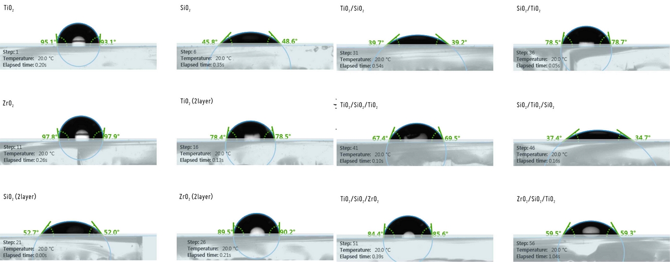
일반적으로 광학박막의 접촉각을 측정할 경우 증착된 직후 측정하는데 본 실험의 경우 안경렌즈나 광학기기 등에 적용하기 위한 실험이므로 자연상태에서 72시간 노출한 후 접촉각을 측정하였다. Fig. 6은 접촉각 측정기(Kruss Co., DA30)로 측정한 광학박막의 접촉각을 나타낸 이미지이며 Table 3에 광학박막의 두께와 접촉각을 나타내었다.
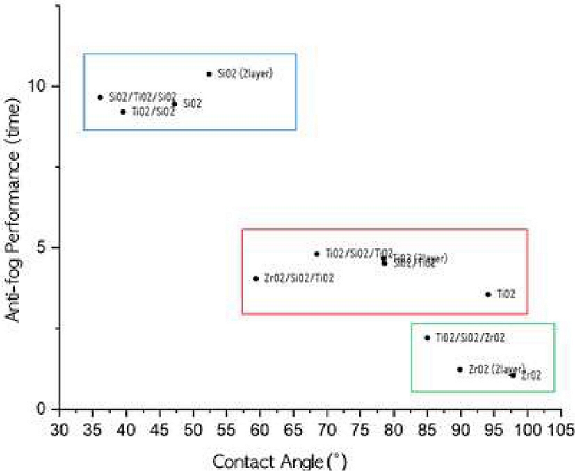
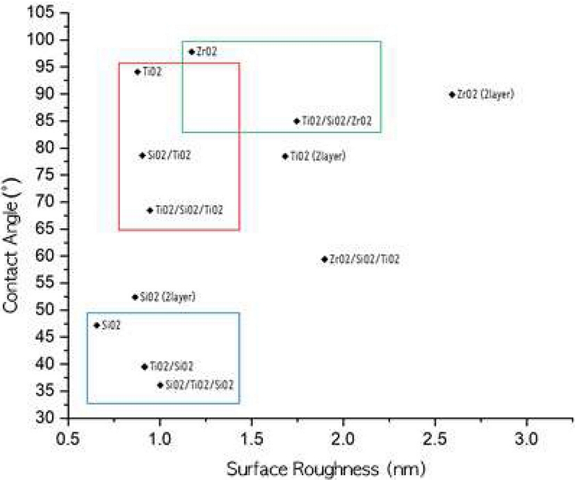
Fig. 7에서 나타난 것과 같이 동일한 증착물질일 경우 표면거칠기가 거칠수록 접촉각이 낮은 친수성향을 갖는 것으로 나타났다. Fig. 8과 같이 친수성향이 큰 SiO2 박막군과 소수성향이 큰 ZrO2 박막군은 안티포그 성능에서 큰 차이를 보였다. 그리고 2 layer 박막은 같은 물질의 단일박막과 비교할 때 접촉각이 낮으며 박막의 두께에 영향을 받음을 확인할 수 있다.
방담(anti-fogging)의 효과를 객관적으로 평가하는 방법으로 EN168 개인용 눈보호구: 비광학적 테스트 방법(personal eye-protection: non-optical test methods)의 흐림에 대한 내성테스트를 많이 활용한다. 분석 시료는 각 시료당 4개를 시험하였으며, 25oC 증류수에 1시간 동안 안정화 후 공기 중 건조하였으며, 48시간 동안 공기 중 전처리 과정을 거쳤다. 내성 테스트의 측정은 물의 온도 50oC의 비커에 시료를 올린 후 시료가 흐려질 때까지의 시간을 측정하였다. 실제 EN168에서는 투과율 초기 값의 80% 이하로 떨어질 때의 시간을 측정하여야 하나 투과율을 측정하기 쉽지 않은 관계로 흐려지기 시작할 때까지의 시간으로 측정하여 Table 4에 나타내었다. 흐림 내성 테스트의 절차대로 흐림이 시작한 후 초기 0.5초는 평가에서 고려하지 않았다. 각 시료의 시간을 측정하여 시간이 길게 나타난 광학박막의 방담효과가 더 우수하다고 할 수 있다. 다만, 이중박막인 TiO2/SiO2, SiO2/TiO2와 다층박막 TiO2/SiO2/ ZrO2, ZrO2/SiO2/TiO2는 기판 뒷면의 반사가 심하여 정확한 측정값으로 보기 어렵다. 측정값에서 알 수 있듯이 접촉각이 가장 작아 친수성이 큰 SiO2의 방담효과가 가장 크고 소수성인 ZrO2의 방담효과가 가장 작음을 알 수 있다. EN168에서는 내성 테스트를 통과하려면 80% 투과율을 유지하고 8초간 유효할 경우 안티포그 성능을 인증한다고 되어 있다. 본 실험에서의 내성 테스트는 완벽하게 실험환경을 갖춘 상태에서 측정한 것이 아니기 때문에 절대적 평가는 어려울 것으로 판단되나 12종의 광학박막의 상대적 평가는 유효하다고 생각된다.
결 론
본 연구에서는 RF 마그네트론 스퍼터링 증착법으로 TiO2, SiO2, ZrO2 단일박막과 이중박막, TiO2/SiO2/ZrO2 다층박막을 만들기 위한 최적 공정조건을 확인하고 광학적, 기계적 특성 등을 분석하여 방담효과를 갖는 광학박막을 규명하고자 하였다. 실험에서는 기판을 슬라이드 글래스를 사용하였으나 실제 안경렌즈나 광학기기 등에 적용하여야 하기 때문에 글로우 방전으로 인한 진공 챔버의 온도가 너무 올라가지 않도록 저진공 분위기로 증착하기 위해 알곤 가스로 진공도는 4.0×10⁻² torr로 유지하였으며, RF 파워 70 W로 약 1시간 정도 스퍼터링을 하면 구현하고자 했던 박막의 두께, 약 100 nm 정도로 증착이 되었다. 이때, 기판과 타겟간의 거리도 중요하게 작용하므로 약 80 mm로 고정한 후 증착하였다.
스퍼터링된 광학박막의 특성을 분석하기 위해 먼저 SEM으로 박막의 단면형태를 확인하고 표면에 고르게 증착되었는지 확인하였고, AFM으로 표면거칠기를 분석하였다. 표면의 화학적 조성을 알아보기 위해 EDS로 광학박막을 분석하였다. 최외층의 물질과 순수 증착물질이 유사하였으며 다층박막의 특성이 최외층 물질의 특성에 영향을 받는다는 것을 알 수 있었다. 박막의 두께는 광투과율을 고려하여 증착하였으나 정밀하게 박막의 두께를 조절하기가 쉽지 않아 설계한 박막의 광투과율과는 다소 차이를 보였다. 방담효과를 측정하기 위해 흐림 내성테스트를 한 결과는 표면거칠기가 크고 접촉각 측정값이 친수성을 갖는 박막이 방담효과가 우수하였다. 안경렌즈에 적용하고자 한 본 실험은 더 두꺼운 박막이나 박막의 열처리를 고려치 않아 강력한 방담효과는 기대하기 어려웠으나 스퍼터링 증착은 기능성 렌즈 등에 활용할 수 있는 우수한 코팅기술임을 확인하였다.
References
- Kim SH, Lee JH, Hwangbo CK. Properties of TiO2 thin films deposited by ion-beam assisted reactive magnetron sputtering. J Korean Vac Soc. 2002;11(3):141-150.
- KISTI(Korea Institute of Science and Technology Information). Recent Study of DLC Coating for Green Automotive Industry, 2013. http://gift.kisti.re.kr/announce/analysis-report/2014/reseat_14018.pdf, (30 August 2019).
-
Mertens J, Hubert J, Vandencasteele N, Raes M, Terryn H, Reniers F. Chemical and physical effect of SiO2 and TiO2 nanoparticles on highly hydrophobic fluorocarbon hybrid coatings synthesized by atmospheric plasma. Surface and Coatings Technology. 2017;315:274-282.
[https://doi.org/10.1016/j.surfcoat.2017.02.040]

-
Zhao Z, Sun J, Xing S, Liu D, Zhang G, Bai L et al. Enhanced Raman scattering and photocatalytic activity of TiO2 films with embedded Ag nanoparticles deposited by magnetron sputtering. J Alloys Compd. 2016;679:88-93.
[https://doi.org/10.1016/j.jallcom.2016.03.248]

-
Adamczyk A. The influence of ZrO2 precursor type on the structure of ZrO2-TiO2-SiO2 gels and selected thin films. J Mol Struct. 2018;1171:706-716.
[https://doi.org/10.1016/j.molstruc.2018.06.068]

-
Wan G, Wang S, Li L, Mu G, Yin X, Zhang X et al. Photocarrier dynamic measurement of rutile TiO2 films prepared by RF magnetron reactive sputtering. J Alloys Compd. 2017;701:549-553.
[https://doi.org/10.1016/j.jallcom.2017.01.146]

- Lee DW, Baek CH, Kim DY, Yang JM, Kim HM, Lee JY. Properties of various hydrophilic thin films deposited on plasma etching glass by RF magnetron sputtering. Proceedings of the Annual Conference of the Korean Vacuum Society. 2012;42:133.
- Noh YA, Kim KC. Transparent hydrophobic anti-reflection coating with SiO2/TiO2 thin layers. J Korea Acad Industr Coop Soc. 2017;18(3):1-6.
-
Lee K, Kim Q, An S, An J, Kim J, Kim B et al. Superwetting of TiO2 by light-induced water-layer growth via delocalized surface electrons. Proc Natl Acad Sci USA. 2014;111(16):5784-5789.
[https://doi.org/10.1073/pnas.1319001111]

- Lee SJ, Lee MK, Park YC. Anti-reflective coating with hydrophilic/ abraion-resistant properties using TiO2/SiOxCy double-layer thin film. J Korean Inst Surf Eng. 2017;50(5):345-351.
-
Nuraje N, Asmatulu R, Cohen RE, Rubner MF. Durable antifog films from layer-by-layer molecularly blended hydrophilic polysaccharides. Langmuir. 2011;27(2):782-791.
[https://doi.org/10.1021/la103754a]

- Choi JY, Eom TY, Park YJ, Choi SH, Kim DH, Cho YJ et al. The effect of electron beam irradiation and Ag buffer layer on the structural, optical, and electrical properties of ZnO/Ag thin films. J Korean Inst Electr Electron Mater Eng. 2018;31(4):221-225.
- Hwangbo CK. Thin film optics, 1st Ed. Seoul: Techmedia, 2016;162-172.
- Cho HJ. Optical thin film practice, 1st Ed. Seoul: Bookshill. 2015;1-17.
- Lee HS, Lee MH. Multilayer coatings on flexible substrate for electromagnetic shielding by using dry/wet hybrid processes. J Korean Inst Surf Eng. 2017;50(5):373-379.
-
Lee HY, Lim UH, Kim JW, Kim WI, Kang AR, Lim CW et al. A study on wearing practice and improvement of personal protective equipment for participant handling livestock carcass infected with virulent avian infectious agents. Korean J Vet Serv. 2015;38(4):241-248.
[https://doi.org/10.7853/kjvs.2015.38.4.241]

- Jeong CS, Jang JW, Kim DY, Bae K, Hong WP. Analysis of ultra-hydrophilic characteristics of SiO2 and TiO2 thin films fabricated by RF-magnetron spuuttering. Proceedings of the Annual Conference of the Korean Vacuum Society. 2011;40:381.
- Lee CH, Jin IH, Choi MK, Bae K, Kim DY, Seo SB et al. Analysis of photocatalytic surface characteristics of oxide thin films with and without plasma etching treatment. Proceedings of the Annual Conference of the Korean Vacuum Society. 2015;48:169.
- Lee S, Im SM, Hwang H. Preparation of superhydrophilic coating solutions containing fluorosurfactants and characterization of their antifogging and antifouling properties. Journal of the Korean Oil Chemists Society. 2017;34(3):525-535.
-
Tao C, Zou X, Du K, Zhou G, Yan H, Yuan X et al. Fabrication of robust, self-cleaning, broadband TiO2-SiO2 double-layer antireflective coatings with closed-pore structure through a surface sol-gel process. J Alloys Compd. 2018;747:43-49.
[https://doi.org/10.1016/j.jallcom.2018.03.008]

-
Lin W, Zheng J, Yan L, Zhang X. Sol-gel preparation of self-cleaning SiO2-TiO2/ SiO-TiO2 double-layer antireflective coating for solar glass. Results in Physics. 2018;8:532-536.
[https://doi.org/10.1016/j.rinp.2017.12.058]

-
Park EJ, Dollinger A, Kim IH, Seo HO, Gantefoer G, Kim YD. Fabrication of a transparent and super-hydrophilic window by depositing WOx nanoparticles via magnetron sputtering onto a glass. Surfaces and Interfaces. 2017;8:8-14.
[https://doi.org/10.1016/j.surfin.2017.04.005]

-
Nezar S, Saoula N, Sali S, Faiz M, Mekki M, Laoufi NA et al. Properties of TiO2 thin films deposited by rf reactive magnetron sputtering on biased substrates. Appl Surf Sci. 2017;395:172-179.
[https://doi.org/10.1016/j.apsusc.2016.08.125]

-
Choi GJ, Jung H, Kim DH, Sohn Y, Gwag JS. Photoelectrocatalytic effect of unbalanced RF magnetron sputtered TiO2 thin film on ITO-coated patterned SiO2 nanocone arrays. Catalysis Science & Technology. 2018;8(3):898-906.
[https://doi.org/10.1039/C7CY02371E]

- Choi MK, Kim DY, Bae K, Baek CH, Kim HM. ETFE hydrophilic properties using RF-magnetron sputtering method. Proceedings of the Annual Conference of the Korean Vacuum Society. 2013;45:149.
-
Wagner P. Anti-fog additives give clear advantage. Plastics, Additives and Compounding. 2001;3(11):18-21.
[https://doi.org/10.1016/S1464-391X(01)80301-9]

-
Magnozzi M, Terreni S, Anghinolfi L, Uttiya S, Carnasciali MM, Gemme G et al. Optical properties of amorphous SiO2-TiO2 multi- nanolayered coatings for 1064-nm mirror technology. Opt Mater. 2018;75:94-101.
[https://doi.org/10.1016/j.optmat.2017.09.043]

-
Shen L, Shen YF, Li F. Optimized utilization of NIR spectrum with interfacial TiO2/SiO2/TiO2 trilayer in hybrid-integrated multijunction architecture. Sol Energ Mat Sol C. 2017;160:425-429.
[https://doi.org/10.1016/j.solmat.2016.11.016]

-
Yang F, Wang P, Yang X, Cai Z. Antifogging and anti-frosting coatings by Dip-layer- by-layer self-assembly of just triple-layer oppositely charged nanoparticles. Thin Solid Films. 2017;634:85-95.
[https://doi.org/10.1016/j.tsf.2017.05.018]

- Hong DW. Antifouling surface coating and application of SI-ARGET ATRP. Polym Sci Tech. 2017;28(5):377-382.
-
Du X, Xing Y, Zhou M, Li X, Huang H, Meng XM et al. Broadband antireflective superhydrophilic antifogging nano-coatings based on three-layer system. Micropor Mesopor Mat. 2018;255:84-93.
[https://doi.org/10.1016/j.micromeso.2017.07.017]

-
Yang F, Cai Z, Wang P, Yang X. Spin-LbL assembled coatings of SiO2 and TiO2 oppositely charged nanoparticles for superhydrophilicity, antifogging and anti-reflection. J Nanotechnol Mater Sci. 2017;4(2):48-52.
[https://doi.org/10.15436/2377-1372.17.1552]

-
Liu Y, Chen J, Peng L, Han J, Deng N, Ding W et al. Improved optical properties of switchable mirrors based on Pd/Mg-TiO2 films fabricated by magnetron sputtering. Mater Design. 2018;144:256-262.
[https://doi.org/10.1016/j.matdes.2018.02.023]

- Park JC, Joung YH, Kang SJ. Electrical and optical properties of the IZTO thin film deposited on PET substrates with SiO?buffer layer. Journal of Korea Institute of Information and Communication Engineering. 2017;21(3):578-584.
- Park MC, Jung BY, Lee JG, Joo KB, Lee WJ. The study of the characteristic of Ti thin film using small magnetron sputtering method for sunglass lens. J Korean Ophthalmic Opt Soc. 2008;13(1):59-63.
- Kim KT, Park YS. Fabrication and characteristics of Ni doped carbon thin films prepared by unbalanced magnetron sputtering for the application of biomaterials. J Korean Inst Electr Electron Mater Eng. 2018;31(1):40-43.

